Spatial Index: Tessellation
Brewing! this post a continuation of Spatial Index: Grid Systems where we will set the foundation for tessellation and delve into the details of Uber H3
0. Foundation
Tessellation or tiling is the process of covering/dividing a space into smaller, non-overlapping shapes that fit together perfectly without gaps or overlaps. In spatial indexing, tessellation is used to break down the Earth's surface into manageable units for efficient data storage, querying, and analysis.
The rationale behind why a geographical grid system (Tessellation system) is necessary: The real world is cluttered with various geographical elements, both natural and man-made, none of which follow any consistent structure. To perform geographic algorithms or analyses on it, we need a more abstract form.
Maps are a good start and are the most common abstraction, with which most people are familiar. However, maps still contain all sorts of inconsistencies. This calls for a grid system, which takes the cluttered geographic space and provides a more clean and structured mathematical space, making it much easier to perform computations and queries.
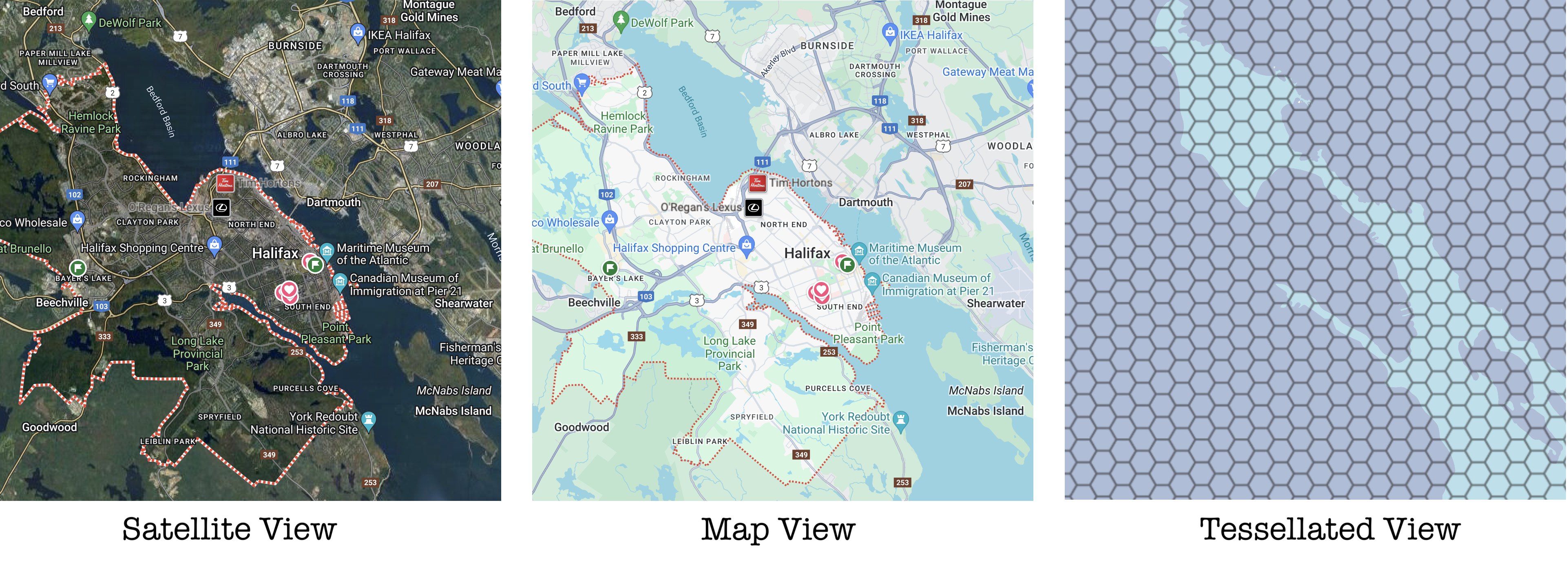
Figure 0: Tessellated View of Halifax
The primary principle of the grid is to break the space into uniform cells. These cells are the units of analysis used in geographic systems. Think of it as pixels in an image.
A grid system adds a couple more layers on top of this, consisting of a series of nested grids, usually at increasingly fine resolutions. They include a way to uniquely identify any cell in the system. Other common grid systems include Graticule (latitude and longitude), Quad Key (Mercator projection), Geohash (Equirectangular projection) and Google S2 (Spherical projection).
1. Uber H3 - Intuition
Most systems use four-sided polygons (Square, Rectangle and Quadrilateral). H3 is the grid system developed by Uber, which uses hexagon cells as its base. It covers the space/world with hexagons and has different levels of resolution, with the smallest cells representing about 1 cm² of space.
1.1. Why Hexagons?
Starting off by adding rules or needs for choosing a tile, such as:
- (a) Uniform shape
- (b) Uniform edge length
- (c) Uniform angles
Brings down the number of options, with the most commonly used shapes being squares, equilateral triangles, and hexagons.
Figure 1: Triangle vs Square vs Hexagon (neighbors)
Another important property of tiles is uniform adjacency, i.e., how unambiguous the neighbors are. For example, squares have 4 unambiguous neighbors but also have 4 ambiguous neighbors at the corners, which may not provide the best perception of neighbors if you consider a circular radius.
Equilateral triangles are much worse, with 3 unambiguous neighbors and 9 ambiguous neighbors, which is one of the reasons why triangles are not commonly used, along with the rotation of cells necessary for tessellation. Lastly, hexagons are the best, with 6 unambiguous neighbors and a structure very close to finding neighbors by radius.
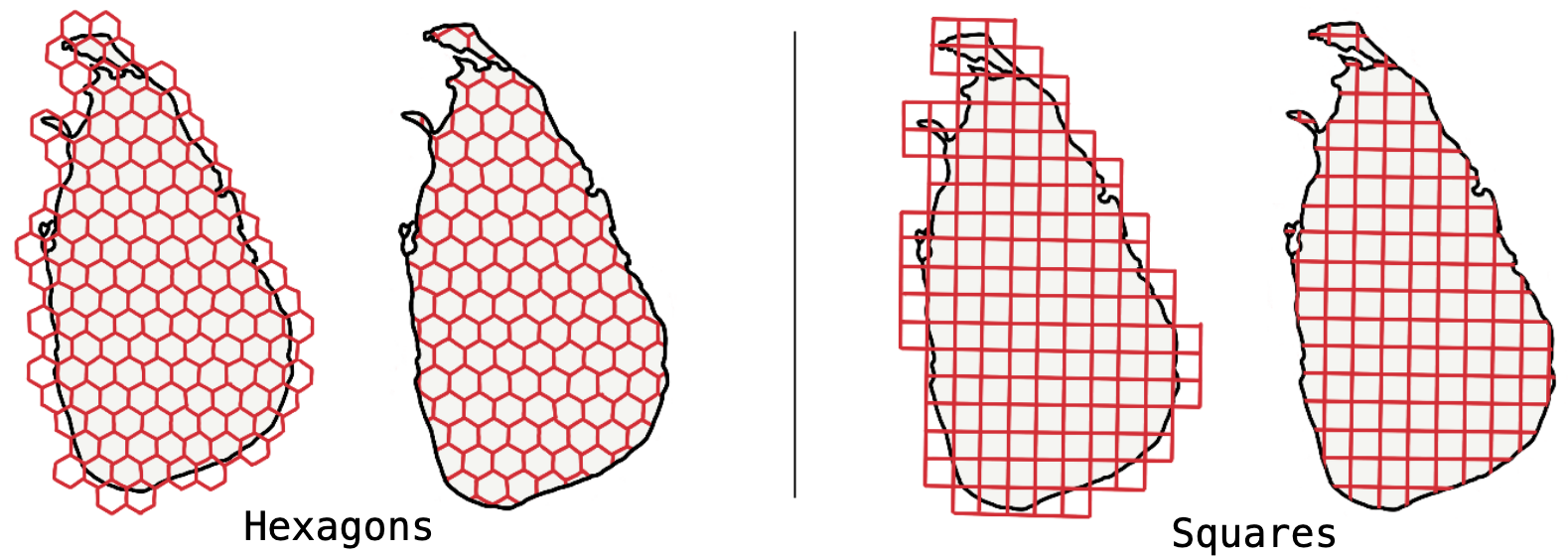
Figure 2: Square vs Hexagon (Optimal Space-Filling)
Hexagons are more space-efficient and have optimal space-filling properties. This means that when filling a polygon with uniform cells, hexagons generally result in less over/under filling compared to squares.
Figure 3: Square vs Hexagon (Child Containment)
Hierarchical relationships between resolutions are another important property. Evidently, squares have hierarchical relationships with perfect child containment and can use algorithms such as quad trees to navigate up and down the hierarchy and space-filling curves to traverse the grid. Hexagons, while not having perfect child containment, can still function effectively with a tolerable margin of error.
Without taking triangles into account, the summary of the comparison between squares and hexagons:
Figure 4: Squares vs Hexagons (Full Comparison)
More on Hexagons vs Squares at Conceptualization of a Cartogram
1.2. Why Icosahedron?
Lastly, low shape and area distortion is more related to the projection than the shape of the tile. There are many types of projections, but the most commonly used are polyhedra. One such projection is the cylindrical projection, used in Geohash, which works well for squares but has the problem of distortion near the poles, making it hard to get equal surface area cells across the projection.

Figure 5: Uniform Shape Polyhedrons
The smaller the face, the lesser the distortion. An icosahedron, with 20 faces, is the better option among the uniform-face polyhedrons for fitting hexagons and triangles on them. Fitting squares on an icosahedron or even a tetrahedron is not ideal. Squares are mostly suitable for cubes (as seen in S2). Taking the best of both worlds, an icosahedron with hexagons is the way to go.
1.3. H3 Grid System
Putting it all together, we take the polyhedron, the icosahedron, project it on the surface of the Earth, then each face on the icosahedron is split into hexagon cells. More specifically, 4 full hexagon cells are completely contained by the face, 3 cells are half contained, and 3 corners form the pentagon.
Each hexagonal cell can be further subdivided into 7 hexagon cells with marginal error for containment. The number of levels decides the resolution.
Figure 6: H3 Projection and Tessellation
The H3 grid system divides the surface of the Earth into 122 (110 hexagons and 12 icosahedron vertex-centered pentagons) base cells (resolution 0), which are used as the foundation for higher resolution cells. Each base cell has a specific orientation relative to the face of the icosahedron it is on. This orientation determines how cells at higher resolutions are positioned and indexed.
1.4. Why Pentagons?
Looking at the icosahedron, the 5 faces come together at every vertex, and truncating that creates the base cell. Pentagons are unavoidable at the vertices. However, there are only 12 of them at every resolution. But again, for most cases dealing with spaces within a city where the resolution is higher than 9, the pentagons, if far off in the water, they are safe to ignore.
Figure 7: Dymaxion layout (12 Vertices in Water)
While the layout of the faces on the icosahedron can be done in any fashion, H3 uses the layout developed by Buckminster Fuller called the Dymaxion layout.
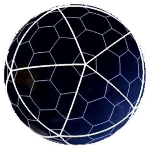
Figure 8: H3 Projection and Tessellation (Animated)
The benefit is that all the vertices end up in the water. For most applications, land is more important than water, and since the vertices are in the water, it reduces the need to deal with pentagons.
1.5. Cell ID
A cell ID is a 64-bit integer that uniquely identifies a hexagonal cell at a particular resolution. The composition of an H3 cell ID is as follows:
- Mode (4 bits): Identifies the H3 mode, which indicates the type of the identifier. For cell IDs, this value defaults set to 1.
- Edge Mode (Reserved, 3 bits): Indicates the edge mode, which is 0 for cell IDs.
- Resolution (4 bits): Specifies the resolution of the cell. H3 supports resolutions from 0 (coarsest) to 15 (finest).
- Base Cell (7 bits): Identifies the base cell, which is one of the 122 base cells that form the foundation of the H3 grid.
- Cell Index (45 bits): Contains the specific index of the cell within the base cell and resolution.
This structure (Figure 14) allows H3 to efficiently encode the hierarchical location and resolution of each hexagonal cell in a compact 64-bit integer.
2. H3 - Implementation
The implementation below, loosely follows the steps of the actual H3 index calculation for demonstration purposes (to better understand the H3 Index). Here's a step-by-step process with reasonable simplifications:
2.1. LatLong to Vec3D
Convert latitude and longitude to 3D Cartesian coordinates using the formulas (similar to Section 4.2.1 in S2):.
Figure 9: (lat, long) to (x, y, z) Transformation
2.1a. LatLong to Vec3D - Snippet
private static double[] latLonToVec3D(double lat, double lon) {
    double r = Math.cos(Math.toRadians(lat));
    double x = r * Math.cos(Math.toRadians(lon));
    double y = r * Math.sin(Math.toRadians(lon));
    double z = Math.sin(Math.toRadians(lat));
    return new double[]{x, y, z};
}
2.2. Icosahedron Properties
We can identify the 12 vertices of the icosahedron using the golden ratio (ϕ). It a well known property of a regular icosahedron, where three mutually perpendicular rectangles of aspect ratio (ϕ) are arranged such that they share a common center.
The icosahedron has 12 vertices, 20 faces, and 30 edges. The 12 vertices are given by: (±1, ±ϕ, 0), (±ϕ, 0, ±1), (0, ±1, ±ϕ). Lastly, the vertices need to be normalized to lie on the surface of a unit sphere.
Figure 10: Golden Ratio Rectangles
To calculate the 20 face centers of the icosahedron:
For each face, average the coordinates of its three vertices and normalize the resulting vector to lie on the unit sphere. Use the formula:
Figure 11: Icosahedron Face Center
2.2a. Icosahedron Vertices - Snippet
double PHI = (1.0 + Math.sqrt(5.0)) / 2.0;
double[][] vertices = {
        {-1, PHI, 0}, {1, PHI, 0}, {-1, -PHI, 0}, {1, -PHI, 0},
        {0, -1, PHI}, {0, 1, PHI}, {0, -1, -PHI}, {0, 1, -PHI},
        {PHI, 0, -1}, {PHI, 0, 1}, {-PHI, 0, -1}, {-PHI, 0, 1}
};

// Normalize the vertices to lie on the unit sphere
for (int i = 0; i < vertices.length; i++) {
    vertices[i] = normalize(vertices[i]);
}
// Computes the center of a face defined by three vertices.
private static double[] computeFaceCenter(double[] a, double[] b, double[] c) {
    double[] center = new double[3];
    center[0] = (a[0] + b[0] + c[0]) / 3.0;
    center[1] = (a[1] + b[1] + c[1]) / 3.0;
    center[2] = (a[2] + b[2] + c[2]) / 3.0;
    return normalize(center);
}
// Normalizes a vector to lie on the unit sphere.
private static double[] normalize(double[] v) {
    double length = Math.sqrt(v[0] * v[0] + v[1] * v[1] + v[2] * v[2]);
    return new double[]{v[0] / length, v[1] / length, v[2] / length};
}
2.3. Vec3D to Vec2D
The Vec2D represents the cartesian coordinates on the face of the icosahedron. It provides a 2D projection (Figure 7) of a point on the spherical surface of the Earth onto one of the icosahedron's faces, used to map geographic coordinates (latitude and longitude) onto a planar hexagonal grid. The conversion involves gnomonic projection, which translates 3D coordinates to a 2D plane by projecting from the center of the sphere to the plane tangent to the face of the icosahedron.
- Calculate
r(Radial Distance): Convert the distance from the face center to an angle using the inverse cosine function. - Gnomonic Scaling: Scale the angle
rfor the hexagonal grid at the given resolution. - Calculate θ (Azimuthal Angle): Determine the angle from the face center, adjusting for face orientation and resolution.
- Convert to local 2D Coordinates: Transform polar coordinates
(r, θ)into Cartesian coordinates(x, y).
Figure 12: Gnomonic Projection (XYZ to rθ)
2.3a. Vec3D to Vec2D - Snippet
// faceAxesAzRadsCII: Icosahedron face `ijk` axes as azimuth in radians from face center to vertex
// faceCenterGeo: Icosahedron face centers in lat/lng radians.
// RES0_U_GNOMONIC: Scaling factor from `Vec2d` resolution 0 unit length (or distance between adjacent cell center points on the plane) to gnomonic unit length.
// SQRT7_POWERS: Power of √7 for each resolution.
// AP7_ROT_RADS: Rotation angle between Class II and Class III resolution axes: asin(sqrt(3/28))

public Vec2d toVec2d(int resolution, int face, double distance) {
    // cos(r) = 1 - 2 * sin^2(r/2) = 1 - 2 * (sqd / 4) = 1 - sqd/2
    double r = acos(1.0 - distance / 2.0);
    if (r < EPSILON) {
        return new Vec2d(0.0, 0.0);
    }

    // Perform gnomonic scaling of `r` (`tan(r)`) and scale for current
    r = (tan(r) / RES0_U_GNOMONIC) * SQRT7_POWERS[resolution];

    // Compute counter-clockwise `theta` from Class II i-axis.
    double theta = faceAxesAzRadsCII[face][0] - this.azimuth(faceCenterGeo[face]);

    // Adjust `theta` for Class III.
    if ((resolution % 2) != 0) {
        theta -= AP7_ROT_RADS;
    }

    // Convert to local x, y.
    return new Vec2d(r * cos(theta), r * sin(theta));
}
About SQRT7_POWERS. Each resolution beyond 0 is created using an aperture 7 resolution spacing, i.e. number of cells in the next finer resolution (Figure 1 and 3). So, as resolution increases, unit length is scaled by sqrt(7). H3 has 15 resolutions/levels (+resolution 0).
2.4. Vec2D to FaceIJK
Hexagonal grids have three primary axes, unlike the two we have for square grids. In Axial coordinates or the Cube coordinates, the three coordinates (i, j, k) ensure that any point in the hexagonal grid can be described without ambiguity.
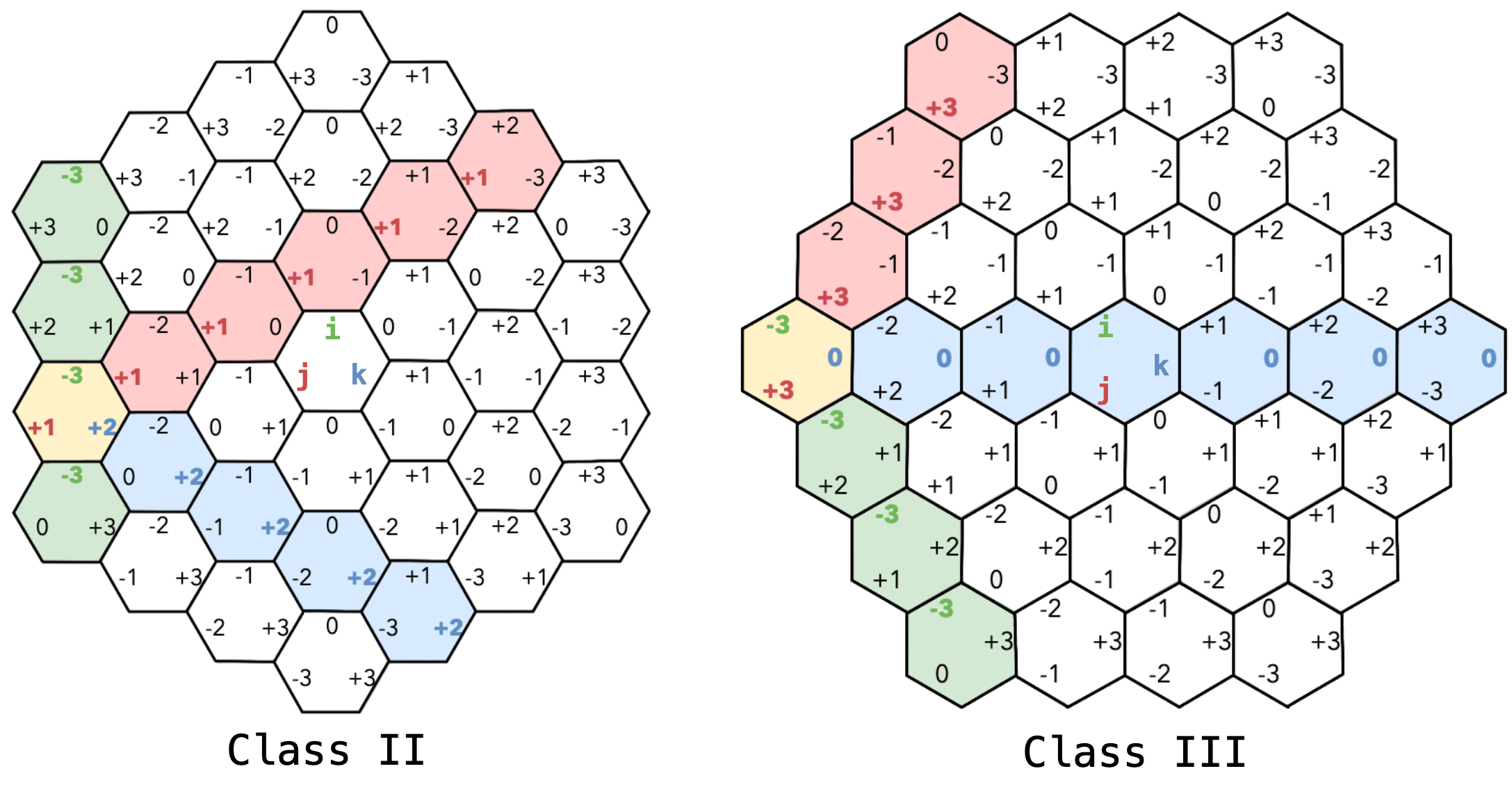
Figure 13: Axial Coordinates (Class II and Class III)
There are several other hex coordinate systems based, in this case, the constraints are i + j + k = 0, with 120° axis separation.
The faceIJK represents the position/location of a hexagon within a face of the icosahedron using three coordinates (i, j, k).
- Reverse Conversion: Translate Cartesian coordinates into the hexagonal coordinate system by aligning them with the hex grid's axes.
- Quantize and Round: Convert floating-point coordinates to integer grid positions, determining the closest hexagon center.
- Check Hex Center and Round: Use remainders to accurately determine which hexagon the point falls into by rounding to the nearest hex center.
// Determine i and j based on r1 and r2
IF r1 < 0.5 THEN
    IF r1 < 1 / 3 THEN
        i = m1
        j = m2 + (r2 >= (1 + r1) / 2)
    ELSE
        i = m1 + ((1 - r1) <= r2 && r2 < (2 * r1))
        j = m2 + (r2 >= (1 - r1))
ELSE IF r1 < 2 / 3 THEN
    j = m2 + (r2 >= (1 - r1))
    i = m1 + ((2 * r1 - 1) >= r2 || r2 >= (1 - r1))
ELSE
    i = m1 + 1
    j = m2 + (r2 >= (r1 / 2))
IF value.x < 0 THEN
    offset = j % 2
    axis_i = (j + offset) / 2
    diff = i - axis_i
    i = i - 2 * diff - offset

IF value.y < 0 THEN
    i = i - (2 * j + 1) / 2
    j = -j
i + j + k = 0.2.4a. Vec2D to FaceIJK - Snippet
public static CoordIJK fromVec2d(Vec2d value) {
    int k = 0;

    double a1 = Math.abs(value.x);
    double a2 = Math.abs(value.y);

    // Reverse conversion
    double x2 = a2 / SIN60;
    double x1 = a1 + x2 / 2.0;

    // Quantize and round
    int m1 = (int) x1;
    int m2 = (int) x2;

    double r1 = x1 - m1;
    double r2 = x2 - m2;

    int i, j;
    if (r1 < 0.5) {
        if (r1 < 1.0 / 3.0) {
            i = m1;
            j = m2 + (r2 >= (1.0 + r1) / 2.0 ? 1 : 0);
        } else {
            i = m1 + ((1.0 - r1) <= r2 && r2 < (2.0 * r1) ? 1 : 0);
            j = m2 + (r2 >= (1.0 - r1) ? 1 : 0);
        }
    } else if (r1 < 2.0 / 3.0) {
        j = m2 + (r2 >= (1.0 - r1) ? 1 : 0);
        i = m1 + ((2.0 * r1 - 1.0) >= r2 || r2 >= (1.0 - r1) ? 1 : 0);
    } else {
        i = m1 + 1;
        j = m2 + (r2 >= (r1 / 2.0) ? 1 : 0);
    }

    // Fold Across Axes if Necessary
    if (value.x < 0) {
        int offset = j % 2;
        int axis_i = (j + offset) / 2;
        int diff = i - axis_i;
        i = i - 2 * diff - offset;
    }

    if (value.y < 0) {
        i = i - (2 * j + 1) / 2;
        j = -j;
    }

    return new CoordIJK(i, j, k).normalize();
}
Each grid resolution is rotated ~19.1° relative to the next coarser resolution. The rotation alternates between counterclockwise (CCW) and clockwise (CW) at each successive resolution, so that each resolution will have one of two possible orientations as shown in Figure 13: Class II or Class III. The base cells, which make up resolution 0, are Class II.
2.5. FaceIJK to H3 Index
Lastly, the face and face-centered ijk coordinates are converted to H3 Index.
Figure 14: H3 Index Structure
If the resolution is not uptill level 15, rest of the vits are set to 1s, for example: 83001dfffffffff. The binary representation is as below (Figure 15); Index mode = 1 i.e. indexes the regular hexagon type. Resolution = 3; Base Cell = 0; Resolution 1, 2 and 3 are 0, 3 and 5, rest are 1s.
Figure 15: H3 Index Structure (Example: 83001dfffffffff)
This primarily involves coverting to Direction bits, representing the hierarchical path from a base cell to a specific cell at a given resolution. These bits encode the sequence of directional steps taken within the hexagonal grid to reach the target cell from the base cell.
- Handle Base Cell: If the resolution is 0 (base cell), directly set the base cell in the index.
// Convert IJK to Direction Bits
faceIJK.coord = directions_bits_from_ijk(faceIJK.coord, resolution)

// Set the Base Cell
base_cell = get_base_cell(faceIJK)
bits = set_base_cell(bits, base_cell)
// Handle Pentagon Cells
IF base_cell.is_pentagon() THEN
    IF first_axe(bits) == Direction.K THEN
        // Check for a CW/CCW offset face (default is CCW).
        IF base_cell.is_cw_offset(faceIJK.face) THEN
            bits = rotate60(bits, 1, CW)
        ELSE
            bits = rotate60(bits, 1, CCW)
        END IF
    END IF
    FOR i = 0 TO rotation_count DO
        bits = pentagon_rotate60(bits, CCW)
    END FOR
ELSE
    bits = rotate60(bits, rotation_count, CCW)
END IF
k-axis).Since each base cell can be oriented differently (Section 1.3) on the icosahedron's faces, rotations are needed to standardize these orientations. rotation_count refers to the number of 60-degree rotations that need to be applied to the H3 cell index to align it with the canonical orientation of the base cell (also refer).
2.6. Official H3 library
Here's a Java snippet using the official H3 library provided by Uber:
2.7a. Official H3 - Snippet
import com.uber.h3core.H3Core;

public class H3Index {
    public static void main(String[] args) throws Exception {
        H3Core h3 = H3Core.newInstance();
        double lat = 37.7749;
        double lon = -122.4194;
        int resolution = 9;

        long h3Index = h3.geoToH3(lat, lon, resolution);
        System.out.println(Long.toHexString(h3Index));
    }
}
3. H3 - Conclusion
So far, in the Spatial Index Series, we have seen the use of space-filling curves and their application in grid systems like Geohash and S2. Finally, we explored Uber's H3, which falls under grid systems and more specifically relies on tessellation. By now, it's likely clear that H3 indexes are not directly queryable on the database by ranges or prefixes, but they have more importance towards the accuracy of filling a polygon, nearby search by radius, high resolution, and many more.
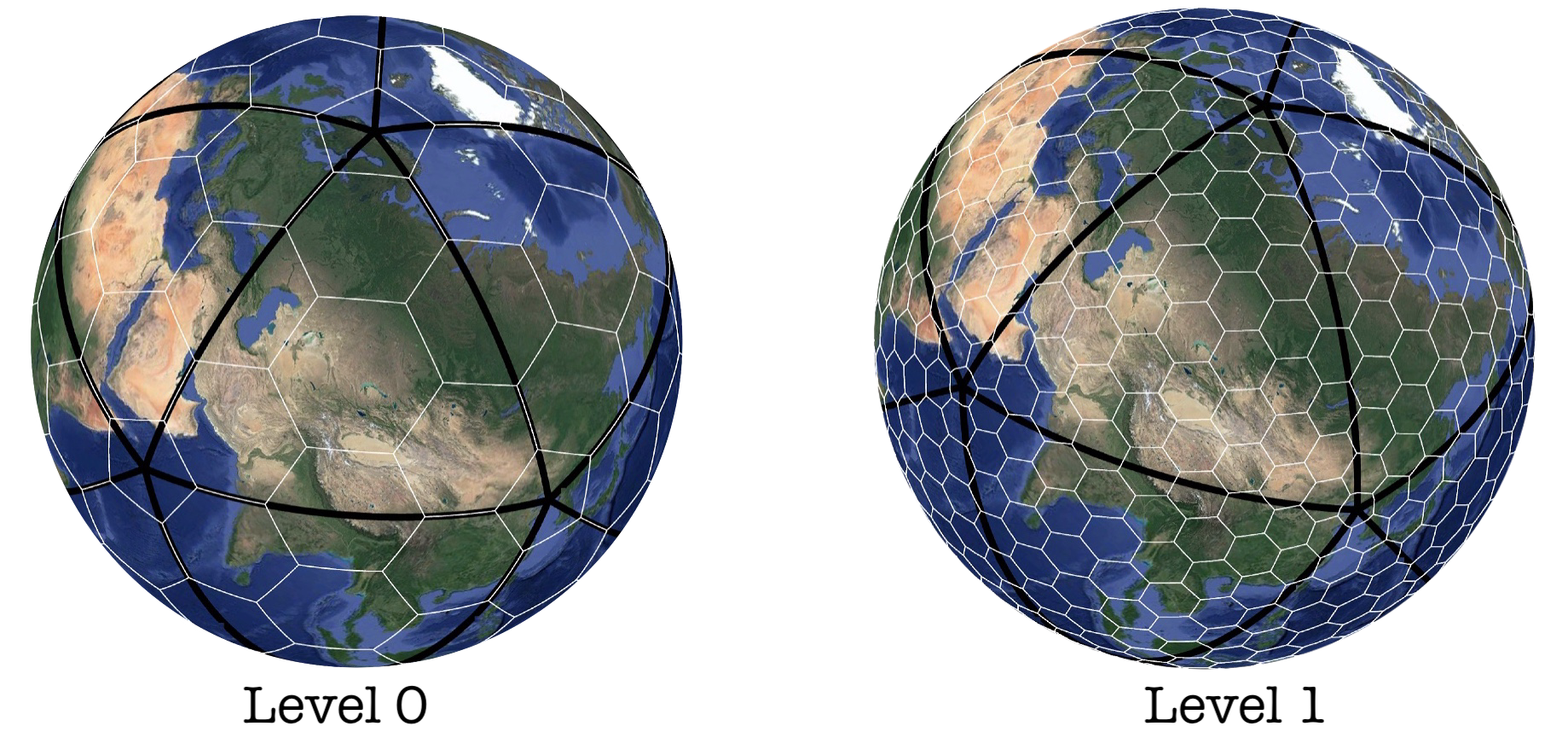
Figure 16: H3 grid segmentation (Level 0 and Level 1)
If you missed the series, it starts with Spatial Index: Space-Filling Curves, followed by Spatial Index: Grid Systems, and finally, the current post, Spatial Index: Tessellation.
4. References
1. Uber Technologies, Inc., "H3: A Hexagonal Hierarchical Spatial Index," GitHub. [Online]. Available: https://github.com/uber/h3.
2. Wikipedia, "Graticule," [Online]. Available: https://en.wikipedia.org/wiki/Graticule.
3. Microsoft, "QuadKey," Microsoft Docs. [Online]. Available: https://learn.microsoft.com/en-us/bingmaps/articles/bing-maps-tile-system.
4. Wikipedia, "Geohash," [Online]. Available: https://en.wikipedia.org/wiki/Geohash.
5. Google, "Google S2 Geometry Library," [Online]. Available: https://s2geometry.io/.
6. Wikipedia, "Icosahedron," [Online]. Available: https://en.wikipedia.org/wiki/Icosahedron.
7. Wikipedia, "Dot product," [Online]. Available: https://en.wikipedia.org/wiki/Dot_product.
8. Wikipedia, "Basis vectors," [Online]. Available: https://en.wikipedia.org/wiki/Basis_(linear_algebra).
9. Wikipedia, "3D Cartesian coordinates," [Online]. Available: https://en.wikipedia.org/wiki/Cartesian_coordinate_system.
10. A. N. Adimurthy, "Spatial Index: Tessellation," PyBlog. [Online]. Available: https://www.pyblog.xyz/spatial-index-tessellation.
11. Wikipedia, "Conceptualization of a Cartogram," [Online]. Available: https://en.wikipedia.org/wiki/Cartogram.
12. Wikipedia, "Golden ratio," [Online]. Available: https://en.wikipedia.org/wiki/Golden_ratio.
13. Wikipedia, "Icosahedron vertices," [Online]. Available: https://en.wikipedia.org/wiki/Icosahedron#Vertices.
14. Wikipedia, "H3: A Hexagonal Hierarchical Spatial Index," [Online]. Available: https://en.wikipedia.org/wiki/H3_(spatial_index).
15. Wikipedia, "Dymaxion map," [Online]. Available: https://en.wikipedia.org/wiki/Dymaxion_map.
16. K. Sahr, "Geodesic Discrete Global Grid Systems," Southern Oregon University. [Online]. Available: https://webpages.sou.edu/~sahrk/sqspc/pubs/gdggs03.pdf.
17. D. F. Marble, "The Fundamental Data Structures for Implementing Digital Tessellation," University of Edinburgh. [Online]. Available: https://www.geos.ed.ac.uk/~gisteac/gis_book_abridged/files/ch36.pdf.
18. J. Castner, "The Application of Tessellation in Geographic Data Handling," Semantic Scholar. [Online]. Available: https://pdfs.semanticscholar.org/feb2/3e69e19875817848ac8694b15f58d2ef52b0.pdf.
19. "Hexagonal Tessellation and Its Application in Geographic Information Systems," YouTube. [Online]. Available: https://www.youtube.com/watch?v=wDuKeUkNLkQ&list=PL0HGds8aHQsAYm86RzQdZtFFeLpIOjk00.
20. Hydronium Labs. "h3o: A safer, faster, and more flexible H3 library written in Rust." GitHub Repository. Available: https://github.com/HydroniumLabs/h3o/tree/master.
Cite this article as: Adesh Nalpet Adimurthy. (Jun 17, 2024). Spatial Index: Tessellation. PyBlog. https://www.pyblog.xyz/spatial-index-tessellation

 #index